Several geometrical features may cause problems for collision
detection code, including the following.
Redundant vertices, edges, and faces
Degenerate faces, including nonconvex or self-intersecting faces and
faces of zero or near-zero area
Incorrect orientation of single-sided faces
Unintended holes, cracks, gaps, and t-junctions between neighboring
faces
Nonplanar faces
Possible approaches to solve the problem.
Welding of vertices
Fixing of cracks between neighboring faces
Merging co-planar faces into a single face
Decomposition into convex (possibly triangular) pieces
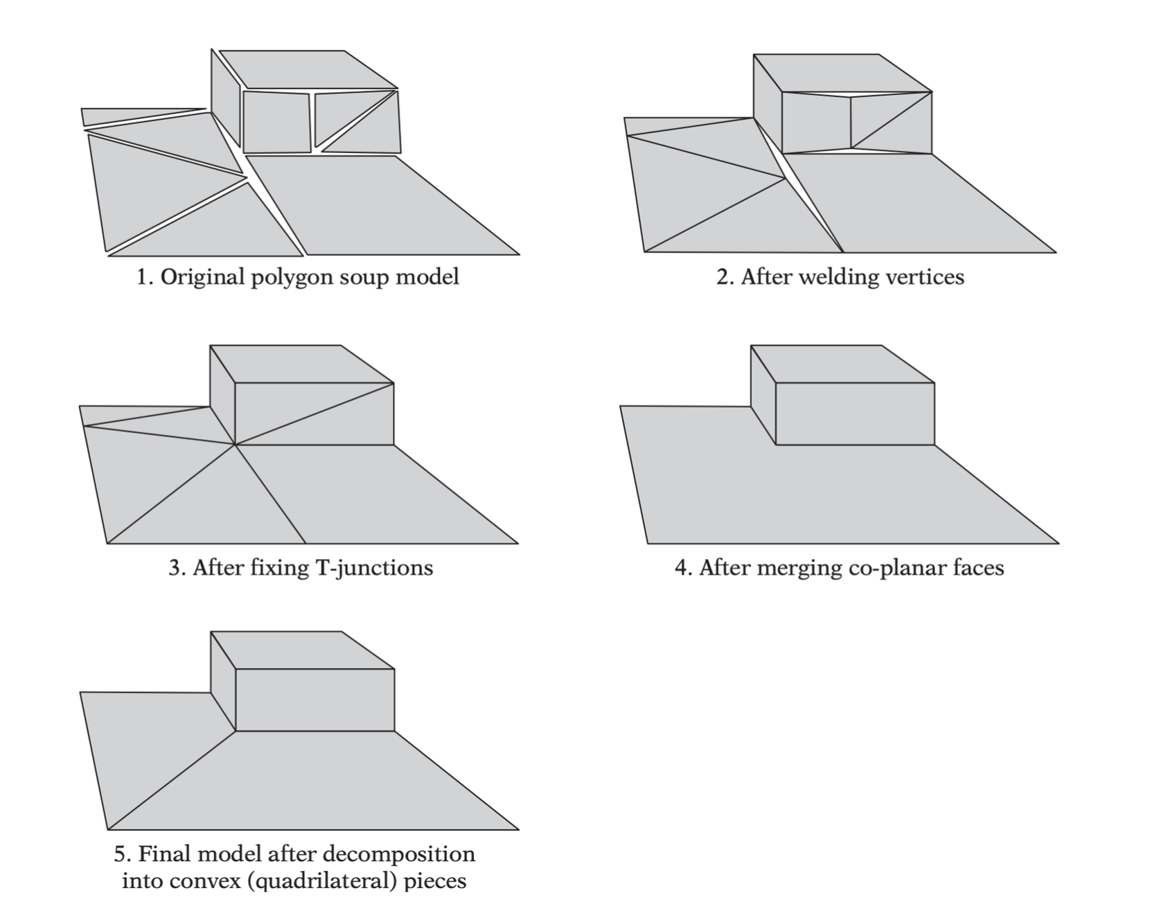
The key steps in turning a polygon soup
into a well-formed robust mesh: vertex welding, t-junction removal,
merging of co-planar faces, and decomposition into convex
pieces.
The key steps in turning a polygon soup into a well-formed robust
mesh: vertex welding, t-junction removal, merging of co-planar faces,
and decomposition into convex pieces.
Vertex Welding
Collision geometry suffers from being built from polygons whose
vertices should have been joined but were not. These duplicate
representations of a single vertex cause cracks between polygons.
Cause ray tests to pass through what was supposed to be solid
geometry.
Ruin the possiblity of maintaining adjacency information between
neighboring faces.
Take up unnecessary space.
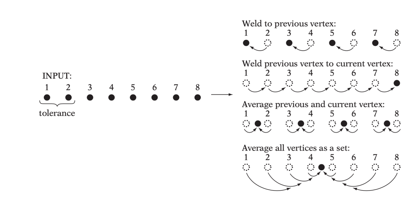
Vertices are considered near when they are within some preset
distance of each other, called the welding tolerance or
the welding epsilon. The space within the welding tolerance of a vertex
is the welding neighborhood of the vertex.
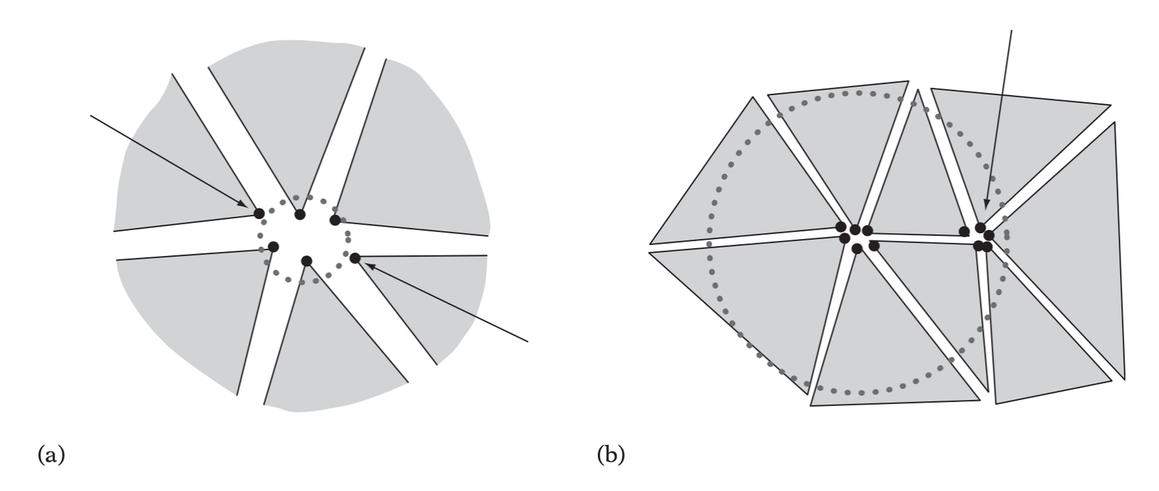
The welding tolerance must be set
appropriately. (a) Too small, and some vertices that should be included
in the welding operation could be missed. (b) Too large, and vertices
that should not be part of the welding operation could be erroneously
included. Arrows indicate vertices incorrectly handled during the
respective welding operations.Different outcomes from alternative
methods for welding a set of points mutually within the welding
tolerance distance.
Computing Adjacency
Information
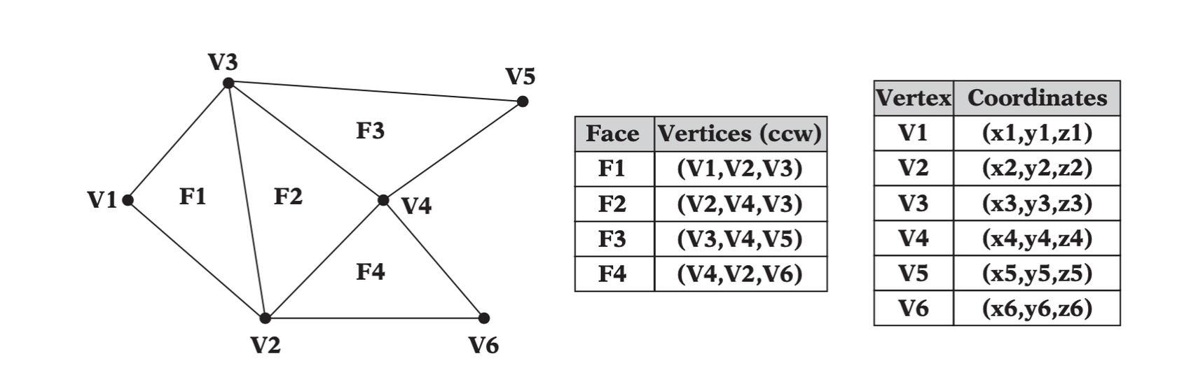
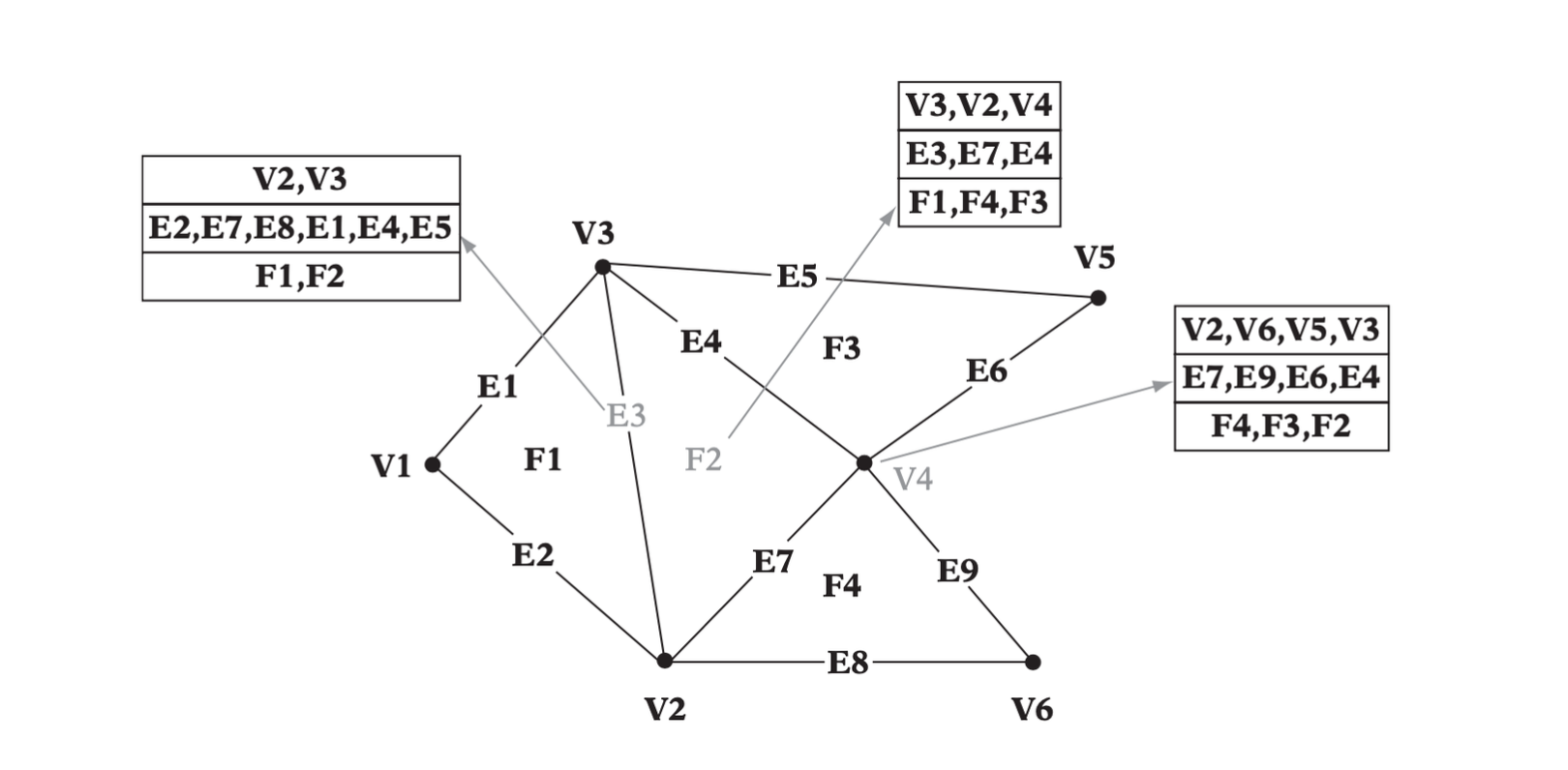
A common geometry representation is the face table representation in
which a table of faces indexes into a table of vertices.
The face and vertex tables for a simple
mesh.Adjacency information associated with
each vertex, edge, and face facilitates instantaneous access to their
adjacent vertices, edges, and faces.
Having full adjacency information allows retrieval of all adjacent
vertices, edges, and faces of a given vertex, edge, or face in constant
\(O(1)\) time.
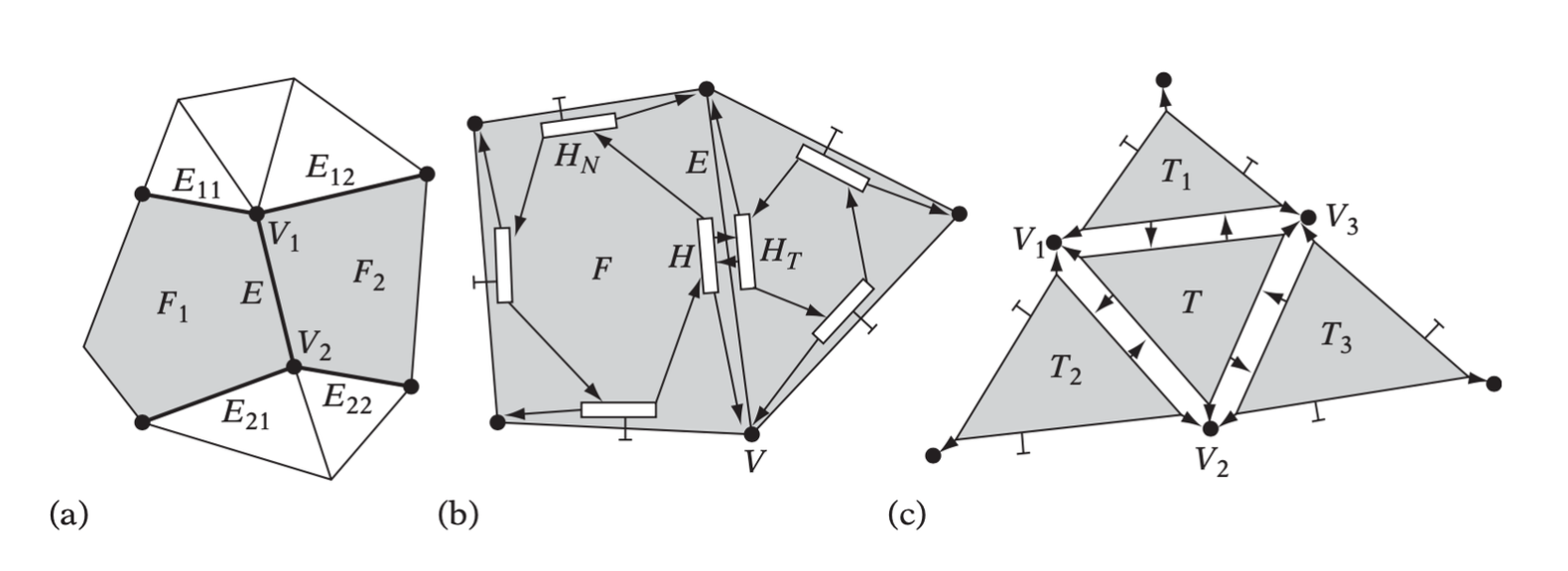
Data associated with (a) the winged-edge
E, (b) the half-edge H, and (c) the winged-triangle
T.
// Basic representation of an edge in the winged-edge representation structWingedEdge { Vertex *v1, *v2; // The two vertices of the represented edge (E) Face *f1, f2; // The two faces connected to the edge Edge *e11, *e12, *e21, *e22; // The next edges CW and CCW for each face };
// Basic representation of a half-edge in the half-edge representation structHalfEdge { HalfEdge *ht; // The matching “twin” half-edge of the opposing face HalfEdge *hn; // The next half-edge counter clockwise Face *f; // The face connected to this half-edge Vertex *v; // The vertex constituting the origin of this half-edge };
// Basic representation of a triangle in the winged-triangle representation structWingedTriangle { Vertex *v1, *v2, *v3; // The 3 vertices defining this triangle WingedTriangle *t1, *t2, *t3; // The 3 triangles this triangle connects to // Fields specifying to which edge (0-2) of these triangles the connection // is made are not strictly required, but they improve performance and can // be stored “for free” inside the triangle pointers int edge1:2, edge2:2, edge3:2; };
Computing a Vertex-to-Face
Table
Locating the faces a given vertex is part of would require an \(O(n)\) pass over all faces. To make this
operation equally fast, a reverse table can be computed: a table taht
for each vertex allows the immediate location of all faces incident to
the vertex.
// Reset the list of triangles associated with each vertex
for (int i = 0; i < MAX_VERTICES; i++) triListHead[i] = NULL;

// Reset the triangle list entry counter
int cnt = 0;
// Loop over all triangles and all three of their vertices
for (int i = 0; i < numTris; i++) {
    for (int j = 0; j < 3; j++) {
        // Get the vertex index number
        int vi = tri[i].vertexIndex[j];
        // Fill in a new triangle entry for this vertex
        triListEntry[cnt].triIndex = i;
        // Link new entry first in list and bump triangle entry counter
        triListEntry[cnt].pNext = triListHead[vi];
        triListHead[vi] = &triListEntry[cnt++];
    }
}
Actually it links triangles of a given vertex to that vertex.
const v2f = {}

_.each(vertices, vertex => {
    v2f[vertex] = []
})

_.each(faces, face => {
    v2f[face.a].push(face)
    v2f[face.b].push(face)
    v2f[face.c].push(face)
})
Computing an Edge-to-Face
Table
The problem is to compute a table that associates an edge with the
faces connected to the edge. Assume that the input mesh is a bounded
manifold. Thus, no edge will be connected to more than two triangles.
The key point is to treat \((A, B)\)
and \((B, A)\) for the same edge.
// Compare vertices lexicographically and return index (0 or 1) corresponding // to which vertex is smaller. If equal, consider v0 as the smaller vertex intSmallerVertex(Vertex v0, Vertex v1){ if (v0.x != v1.x) return v1.x > v0.x; if (v0.y != v1.y) return v1.y > v0.y; return v1.z > v0.z; }
Because edges are represented as a pair of vertex indices and this
pair must be used to index into a table, an open hash table is employed.
The hash key is computed from the two vertex indeces. The key is
associated with a data block, which is defined as below.
structEdgeEntry { int vertexIndex[2]; // The two vertices this edge connects to int triangleIndex[2]; // The two triangles this edge connects to int edgeNumber[2]; // Which edge of that triangle this triangle connects to EdgeEntry *pNext; // Pointer to the next edge in the current hash bucket };
// Reset the hash table
for (int i = 0; i < MAX_EDGES; i++) {
    edgeListHead[i] = NULL;
}

// Reset the edge list entry counter
int cnt = 0;
// Loop over all triangles and their three edges
for (int i = 0; i < numTris; i++) {
    for (int j = 2, k = 0; k < 2; j = k, k++) {
        // Get the vertex indices
        int vj = tri[i].vertexIndex[j];
        int vk = tri[i].vertexIndex[k];
        // Treat edges (vj, vk) and (vk, vj) as equal by
        // flipping the indices so vj <= vk (if necessary)
        if (vj > vk) Swap(vj, vk);
        // Form a hash key from the pair (vj, vk) in range 0 <= x < MAX_EDGES
        int hashKey = ComputeHashKey(vj, vk);
        // Check linked list to see if edge already present
        for (EdgeEntry *pEdge = edgeListHead[hashKey]; ; pEdge = Edge->pNext) {
            // Edge is not in the list of this hash bucket; create new edge entry
            if (pEdge == NULL) {
                // Create new edge entry for this bucket
                edgeListEntry[cnt].vertexIndex[0] = vj;
                edgeListEntry[cnt].vertexIndex[1] = vk;
                edgeListEntry[cnt].triangleIndex[0] = i;
                edgeListEntry[cnt].edgeNumber[0] = j;
                // Link new entry first in list and bump edge entry counter
                edgeListEntry[cnt].pNext = edgeListHead[hashKey];
                edgeListHead[hashKey] = &edgeListEntry[cnt++];
                break;
            }
            // Edge is in this bucket, fill in the second edge
            if (pEdge->vertexIndex[0] == vj && pEdge->vertexIndex[1] == vk) {
                pEdge->triangleIndex[1] = i;
                pEdge->edgeNumber[1] = j;
                break;
            }
        }
    }
}
const e2f = {} _.each(faces, face => { const [a, b] = lexicographicSort(face.a, face.b) const [b, c] = lexicographicSort(face.b, face.c) const [c, a] = lexicographicSort(face.c, face.a) const ab = b.sub(a) const bc = c.sub(b) const ca = a.sub(c)
_.each([ab, bc, ca], edge => { const e = e2f[computeHashKey(edge)] if (!e) { e2f[computeHashKey(edge)] = { edge, facePair: [face], } } else { e.facePair[1] = face } }) })
Holes, Crack, Gaps, and
T-junctions
A hole in a mesh is signified by a set of vertices,
connected by a closed chain of edges in which no faces have been defined
to connect all of these vertices and edges.
A crack is used to refer to narrow wedge-like slots
between two partially connected geometries.
A gap is some narrow voids between two completely
unconnected geometries.
T-junctions or t-joints are
referred as situations in which an endpoint of one edge lying on the
interior of another edge — the vertex usually displaced off the line by
some small amount.
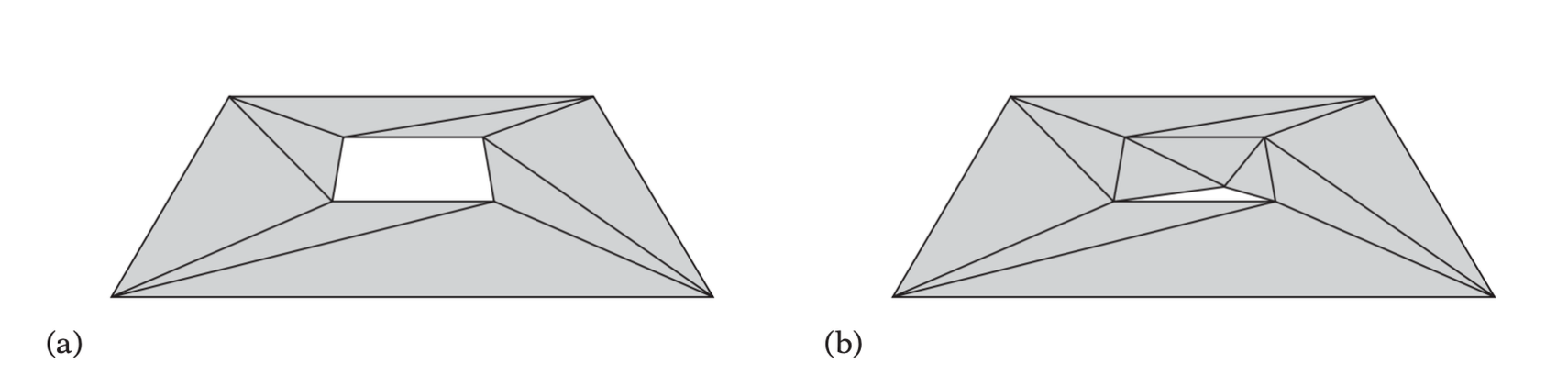
(a) A mesh with an intentional hole. (b)
A mesh with an unintentional hole — a crack (exaggerated).(a) A (nonhole) crack. (b) A gap. (c) A
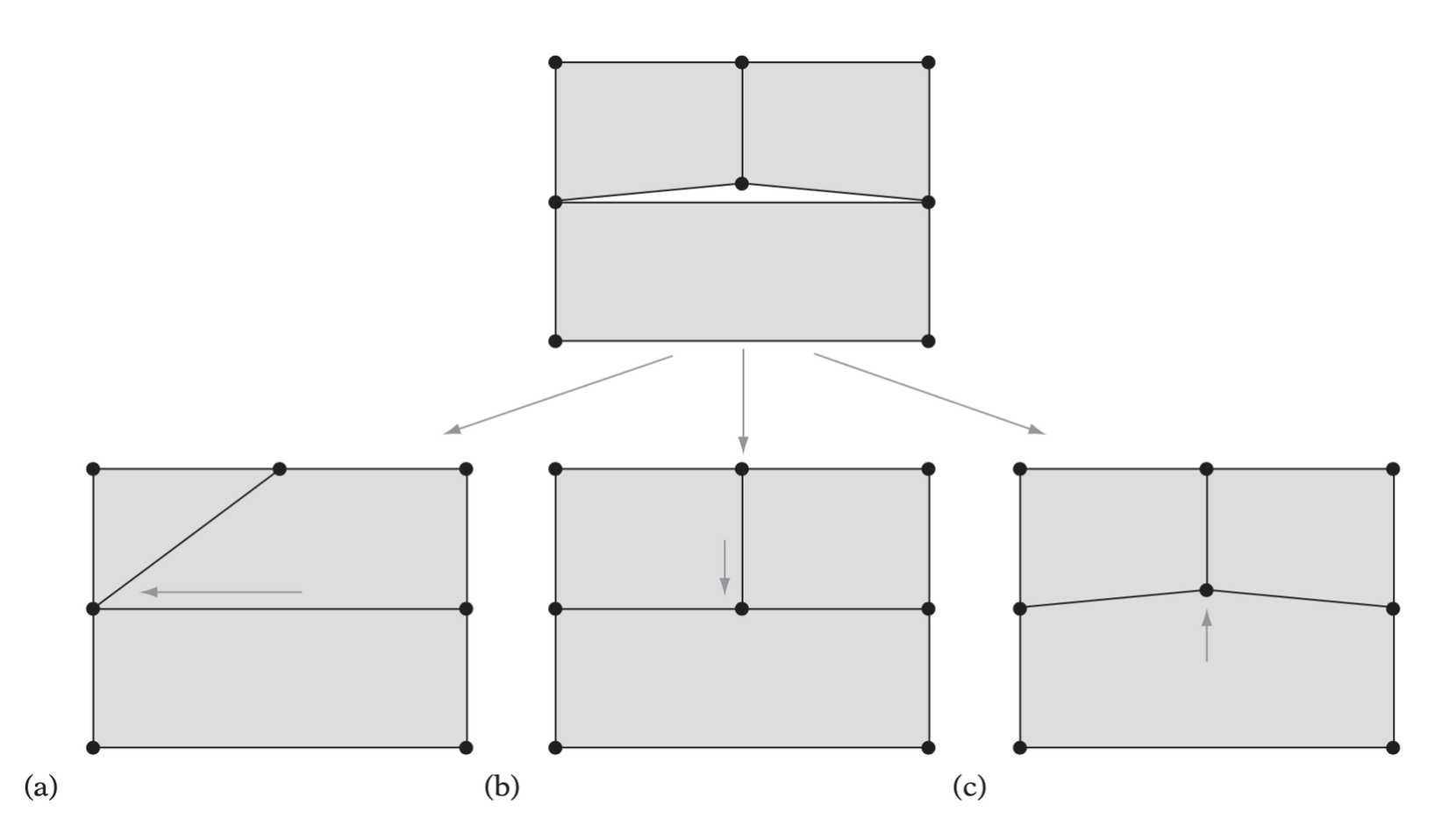
t-junction (and its corresponding t-vertex).Three alternative methods for resolving a
t-junction. (a) Collapsing the t-vertex with a neighboring vertex on the
opposing edge. (b) Cracking the opposing edge in two, connecting the two
new edge endpoints to the t-vertex. (c) Snapping the vertex onto the
opposing edge and inserting it, by edge cracking, into the
edge.